A cooling tower preventive maintenance (PM) inspection gives heating, ventilation and air conditioning (HVAC) technicians two paths to follow: water through the distribution system, fill, basin and suction; air through the louvers, fill and fan stack. Once you trace both paths, most performance and reliability faults become easier to find.
Most induced-draft towers use one of two drive arrangements: a gearbox-driven top fan or a belt-driven counterflow fan with pillow block bearings, sheaves, removable inlet louvers and spray headers above the fill.
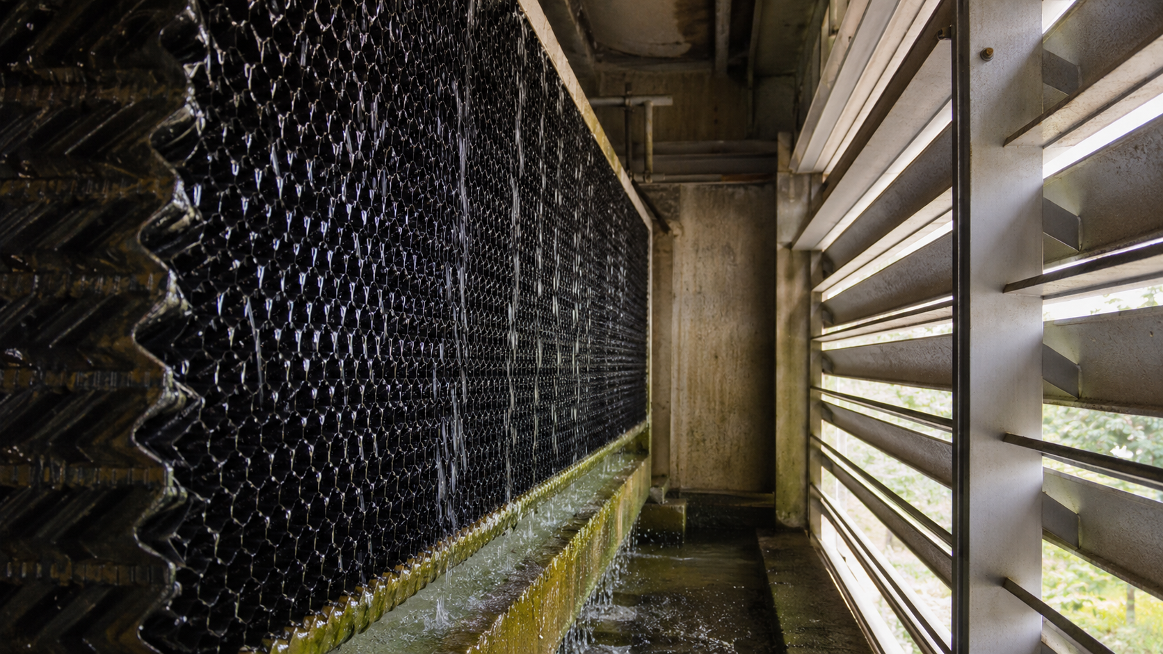
Hot condenser or process water returns from the mechanical room and enters the top of the tower. Spray nozzles or distribution openings spread that water across the fill. The fan pulls air through the tower. Air moves through the fill, either horizontally across the falling water in crossflow towers or upward against the falling water in counterflow towers and carries heat out through the fan discharge and leaves the cooled water in the basin.
From the basin, the system pulls water back through the suction connection and sends it to the equipment. On paired towers, an equalizer line keeps the basin levels matched between cells. A single tower may only have a supply and return, with no equalizer.
Start the inspection by naming the tower type and the water path in front of you. Find the hot-water return, suction, equalizer if present, fill, louvers, fan drive and control point. A few minutes spent on orientation prevents bad assumptions later in the PM.
Cooling towers serve chillers, condensers or process equipment that cannot lose heat rejection without notice. Speak with the building engineer or customer before you shut down the fan, pump or controls. Confirm what the tower serves, how long the site can tolerate shutdown and whether the building automation system (BAS) or a standalone controller owns fan operation.
Use lockout/tagout before opening control panels, removing guards, entering the tower or working around the fan drive. A two-speed motor, variable frequency drive (VFD), BAS command or basin heater circuit can energize equipment while someone works inside the tower. Treat the control cabinet, motor terminal box and heater connections as live until your meter and lockout procedure prove otherwise.
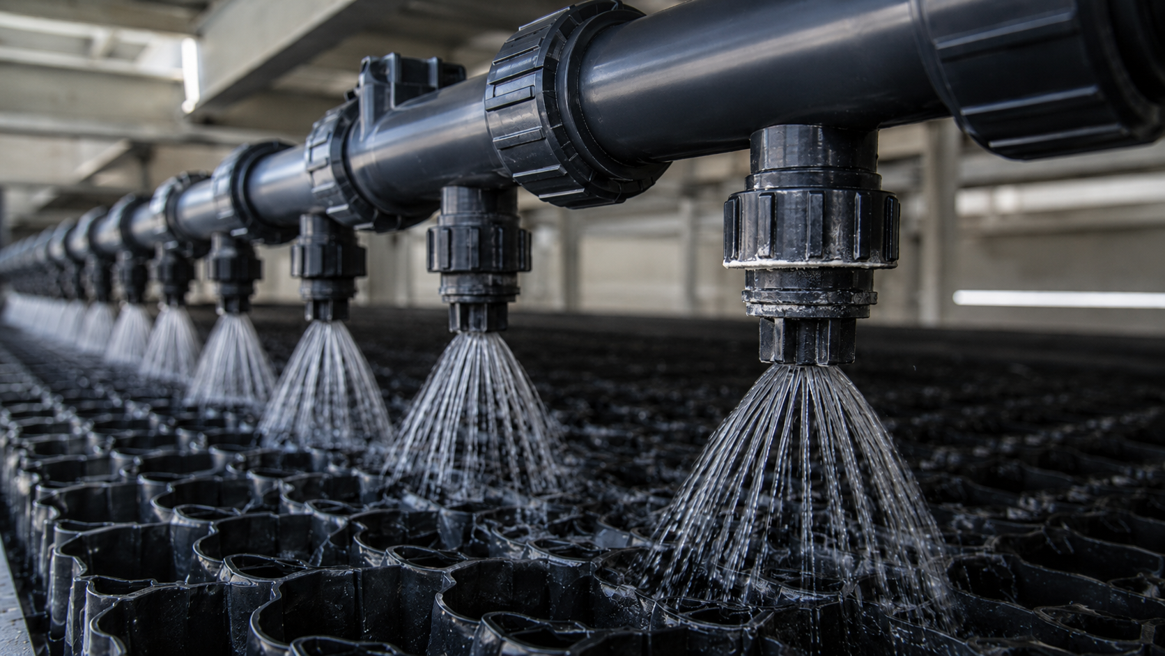
Cooling performance suffers when water fails to reach the fill in an even pattern. Plugged nozzles in the upper distribution area create dry or underfed sections of fill, and the tower loses heat-transfer surface even while the fan runs.
Check spray nozzles with the fan off and the circulation pump running, when the site can support that test. Watch the spray pattern across the header or distribution basin. Look for weak flow, dead spots, nozzles packed with scale or debris and water spilling where it should not.
Clean light blockage with a pick, brazing rod, coat hanger or needle-nose pliers when the nozzle style allows it. Remove and clean nozzles that have heavy scale or debris. Some towers need pressure washing or nozzle removal during a detailed PM. Use the least force that clears the blockage and protects the plastic parts.
Do not change a balancing valve during routine PM unless the lead technician or building engineer asks for it. That valve controls how much water returns to the tower and how the distribution section fills. Too much flow can flood the basin or distribution area. Too little flow leaves the tower short of heat rejection.
Record leaks at distribution flanges, gaskets and rusted bolts. Water trails around those fasteners give the customer a specific repair target before a small leak becomes a casing or structural problem.
Fill gives the tower the surface area it needs for heat transfer. Dirt, algae, scale and broken sections reduce that surface area and restrict air. Pressure wash the fill and nearby walls when the material can handle it. Keep enough distance to clean the surface without cutting or deforming the media. High-pressure water can damage some tower plastics so use low pressure or manufacturer-approved cleaning methods on PVC fill, eliminators and louvers.
Do not confuse inlet air louvers with fill. On many belt-driven counterflow towers, the louvers sit around the outside and the fill sits above and behind them. The louvers guide incoming air and block splash-out. The fill handles the falling water and heat exchange.
Remove louver sections with a method you can reverse. Stack sections in order when the tower uses different sizes. Wash both faces, clear algae and dirt from the passages and reinstall them in the same arrangement. A dirty louver bank can starve the tower of air and keep condenser water temperature high even after the fan runs for long periods.
Look for missing caulk or sealant around panels and fan deck joints. Gaps let air bypass the intended path through the fill and fan stack. Resealing those joints helps the fan pull air where the tower design needs it.
The basin tells you how the tower behaves between PM visits. Mud, biological growth, loose hardware, rust flakes and scale all collect there. Wash the basin walls and floor, then leave enough water for testing float operation and valve response.
Check the makeup water float and valve. Inspect the ball, pins, linkage and moving hardware. Grease exposed moving parts when the valve design allows it and the lubricant will stay above the water line. Test the float by lowering it into the water and letting it rise. The valve opens as the float drops and closes when the basin reaches its set level.
Set basin level with two limits in mind. The water level must cover the suction enough to keep the pump from pulling air. It also must stay below the overflow after shutdown, because water held in the fill and distribution section drains back into the basin when flow stops. Follow the tower manufacturer's level mark when available.
Exercise the supply, return, equalizer and drain valves during PM when site conditions allow it. A valve left in one position can seize when the team needs it for cleaning, isolation or emergency repair.
Note: Follow the site water-management plan and coordinate with the water-treatment provider before cleaning, disinfecting or restarting a tower. Treat heavy biofilm, stagnant water, visible slime or suspected Legionella conditions as a safety issue, not just a housekeeping issue.
The fan section carries much of the tower's mechanical risk. It sits in a wet, vibrating environment and any imbalance can spread through the motor, gearbox, shaft, bearings, blades and support beams.
From the top, inspect the fan guard or inlet screen for cracks, loose sections and rub marks. Vibration can crack screens and guards. Debris on the guard or fan deck can also hint at airflow restrictions or loose material in the stack.
On a gearbox-driven tower, check the motor, coupling, gearbox and fan hub as one drive train. Check gearbox oil at the plug or level point, then compare it with the dipstick if the unit has one. Look for oil around seals and drain plugs. A gearbox can leak from a failed seal, and it can also push oil out if someone overfilled it.
Listen and feel for roughness. If the drive train makes noise and you cannot isolate it, separate the coupling and run the motor by itself under a controlled test. That helps you decide whether the motor, coupling or gearbox creates the noise.
Take vibration readings close to the bearings. On motors, collect inner and outer bearing readings in vertical, horizontal and axial positions where the frame allows access. The axial reading checks movement along the shaft line. On gearboxes, take readings at points that capture bearing and gear condition. Record the readings in the same positions each PM so trends mean something.
If the motor runs on a VFD, check for the site’s specified shaft-current mitigation, such as shaft grounding rings or brushes, insulated bearings, proper bonding and VFD-rated cabling.
Address cracked mechanical beams and rusted hardware early because those faults make vibration worse. A crack near a fan support, gearbox mount or bearing beam can grow, shift alignment and trip the tower at the worst time.
Inspect beams, welds, brackets and fasteners around the motor, gearbox, shaft and bearings. Push or pull on accessible supports to feel for looseness. Record cracked welds, rusted brackets, missing bolts and any movement that does not belong there.
The vibration switch protects the tower when vibration reaches a set trip point. Treat it like a safety control, similar in purpose to a high-pressure safety on other HVAC equipment. Confirm that it mounts tight to the structure, that its reset works and that a controlled bump test trips the circuit when the procedure permits it. A failed vibration switch needs urgent reporting because it removes a layer of protection from the fan drive.
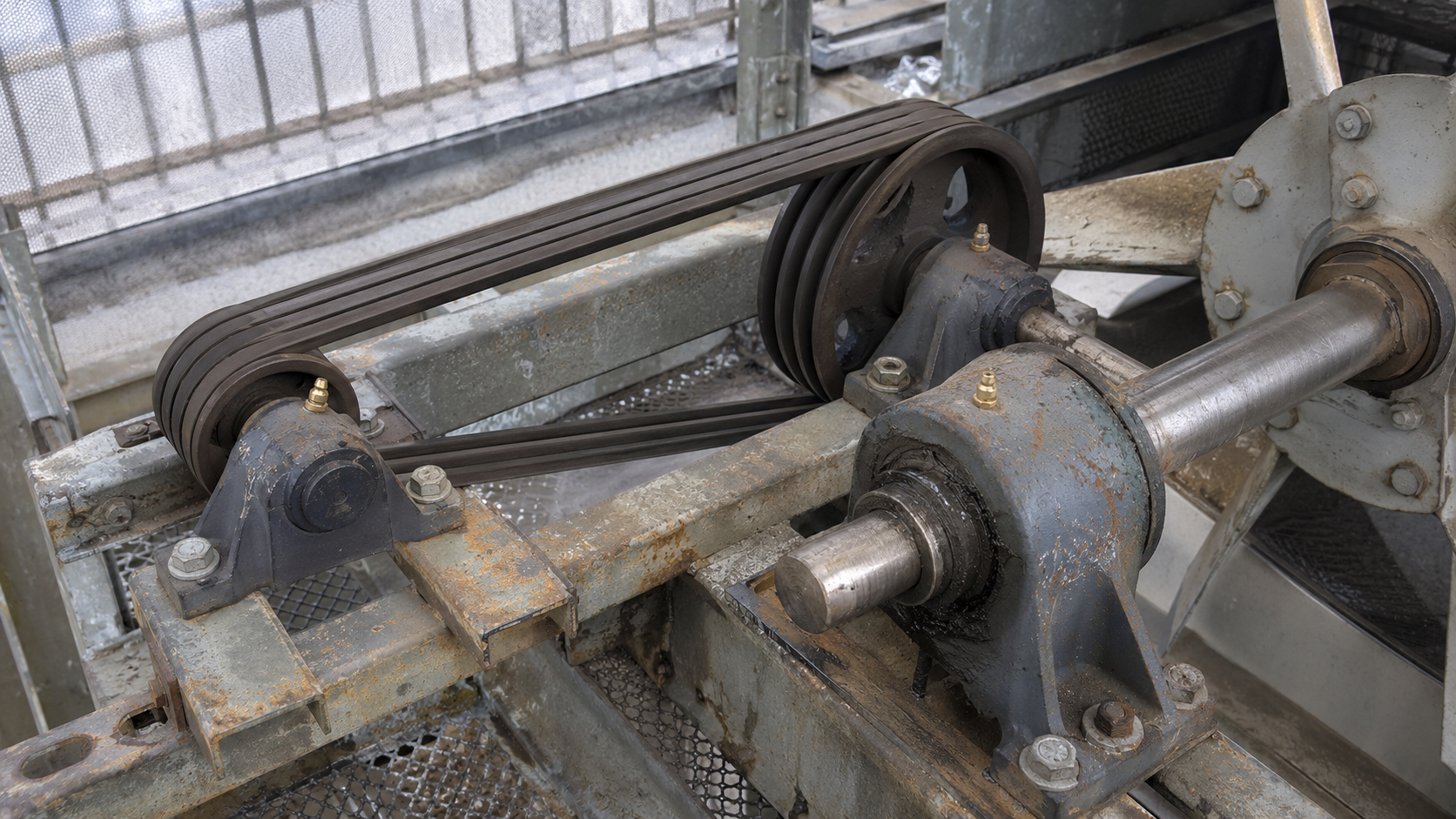
A belt-driven tower adds sheaves, belts, pillow block bearings, grease points and tension hardware to the PM. Start with the fan blades and hub. Inspect blade hardware for corrosion, loose fasteners, missing coating, rub marks and buildup. Uneven buildup on blade surfaces can throw off fan balance.
Check belt tension and alignment. Start with hand pressure and sightline checks, then confirm alignment with a pulley laser. A belt with sag, uneven tracking or sheave misalignment loads the motor and bearings. After belt replacement or tension adjustment, tighten the lock nut on the tension rod so vibration cannot walk the motor frame out of position.
Choose between a notched power band and individual belts based on the tower design and manufacturer guidance. A power band can hold grooves together, but it gives the drive less forgiveness. Individual belts can tolerate small differences between grooves with less stress on the bearings and motor.
Inspect pillow block bearings and grease practice. Remote grease lines can hide failure because a cracked or rubbed line may take grease outside the bearing while the technician thinks grease reached the fitting. When design and access allow, direct grease fittings at the bearing give better control. Follow the tower or bearing manufacturer for grease quantity. Some bearings need only a small measured amount per PM. Treat over-greasing as a serious fault.
Clean old grease from the fitting, cap and bearing area before adding fresh grease. Grease packed around a bearing attracts dirt, holds moisture and slings onto nearby components when the shaft rotates.
Check bearing slingers or guards. These small shields keep water from sitting on the bearing. Without them, water can mix with grease and shorten bearing life. Rotate the shaft by hand after lockout and feel for roughness or play.
Cooling tower controls may live in a standalone temperature controller, a BAS panel, a VFD cabinet or a simple two-speed control box. Learn which system commands the fan before testing anything.
For a two-speed motor, check high and low speed operation against water temperature demand. Inspect contactors, wiring, terminals and sensor inputs. Look for burnt lugs, loose conductors, damaged insulation and contactor voltage drop during an energized test by a qualified technician.
For a BAS or VFD-controlled tower, find out whether the system runs from water temperature, pressure, a proportional-integral-derivative (PID) loop or another sequence. A PM report should state the control strategy you found, the checks you performed and any items you could not test because the building needed the tower online.
Check basin heater operation before freezing weather. Inspect the heater element, contactor, wiring and motor terminal box or heater connection box. Test resistance or contactor operation based on the heater style and site procedure.
An open loop tower sends the circulating water from the basin to the equipment, then returns it to the tower through the spray system and fill. The same water touches air, fill, basin and the process or condenser circuit.
A closed loop tower keeps the building or process fluid inside a heat exchanger. A separate spray pump mounted at the tower moves basin water up to the spray system and over that heat exchanger. The process fluid stays inside the coil or exchanger while the tower water and air remove heat from the outside.
Look for a separate pump and motor mounted on the tower side, piped from the basin to the top spray section. That arrangement points to a closed loop tower in most field checks. An open loop tower may still have pumps, but those pumps sit in the mechanical system and move circulating water between the tower and the equipment.
A PM report gives the customer enough detail to approve repairs without guessing. Record the condition, location and consequence of each finding.
Photograph the fault and one wider shot that shows location. For instance, a close-up of a cracked bracket helps but a second photo showing the bracket near the fan support helps the customer understand risk.
A cooling tower PM should leave the technician with answers to five questions: Does water reach the fill in an even pattern? Does air move through the intended path? Does the fan drive run without abnormal vibration, noise or leakage? Does the basin maintain the right level? Do the controls and safeties protect the equipment?
Answer those questions with inspection notes, readings and photos, and the PM becomes more than a cleaning visit. It becomes a reliability check on the equipment that lets the building or process reject heat.
If you have needs for any cooling tower preventive maintenance, please reach out to us. We are a full service cooling tower manufacturing company that also does retrofits and site audits.